STM32CubeIDE-基本使用

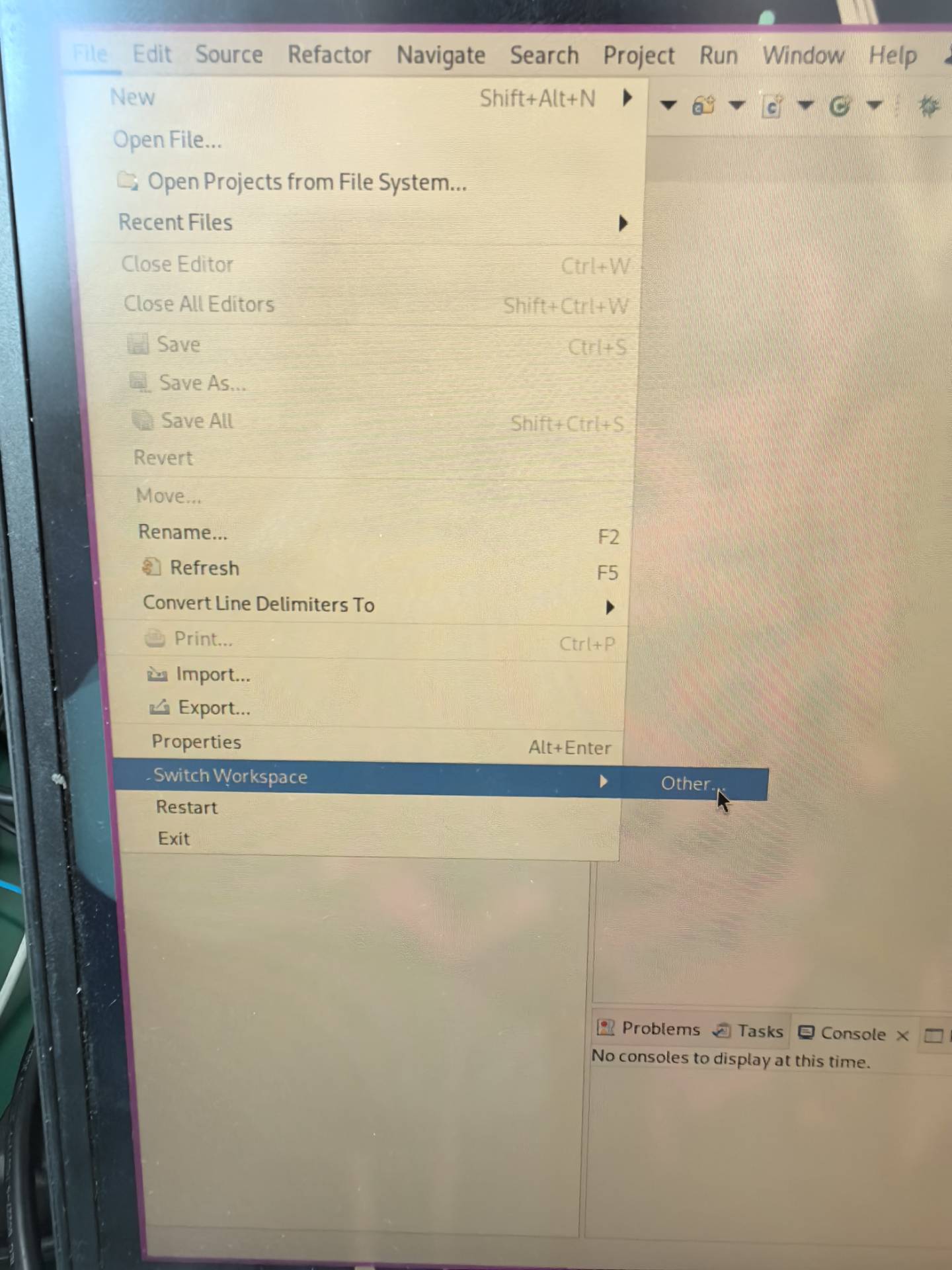
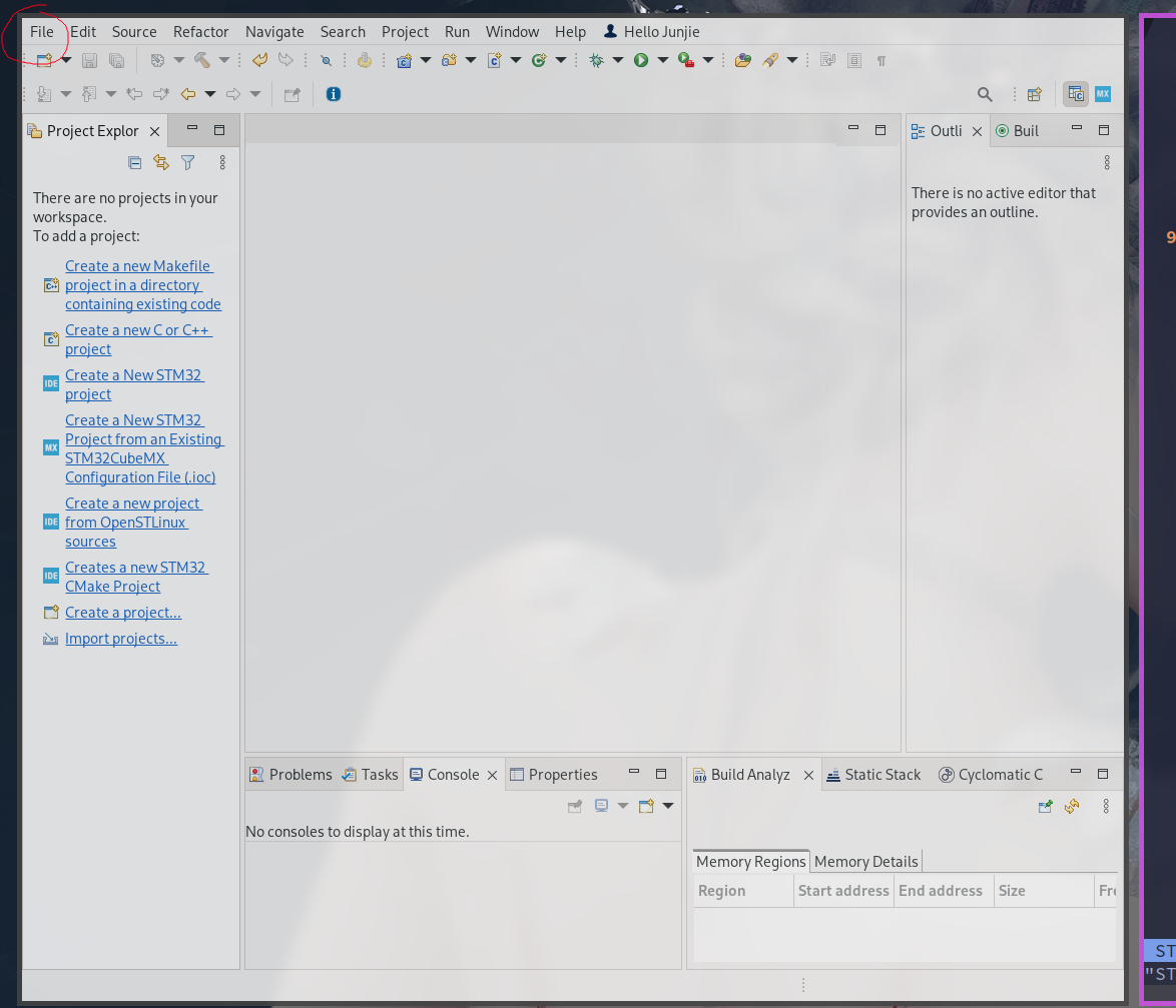
切换 workspace
测试代码 (让绿灯闪烁)

1
2
3
4
5
6
7
8
9
10
11
/* Infinite loop */
/* USER CODE BEGIN WHILE */
while (1)
{
/* USER CODE END WHILE */
HAL_GPIO_TogglePin(GPIOA, GPIO_PIN_5);
HAL_Delay(1000);

/* USER CODE BEGIN 3 */
}
/* USER CODE END 3 */
  • HAL_GPIO_TogglePin() 函数用于 toggle 一个引脚的状态, 第一个参数是 GPIOx, 第二个参数是具体的引脚号如 GPIO_PIN_x
  • HAL_Delay() 函数用于暂停程序的运行

GPIO IN

将引脚设置为 GPIO_input 之后, 按下表示 0, 放手表示 1.

测试, 按下 button 的代码:

1
2
3
4
5
6
7
8
9
10
11
12
  /* Infinite loop */
/* USER CODE BEGIN WHILE */
while (1)
{
if(HAL_GPIO_ReadPin(GPIOC, GPIO_PIN_13)==GPIO_PIN_SET) {
HAL_GPIO_WritePin(GPIOA, GPIO_PIN_5,GPIO_PIN_SET);
}
else {
HAL_GPIO_WritePin(GPIOA, GPIO_PIN_5,GPIO_PIN_RESET);
}
/* USER CODE END WHILE */
}
  • HAL_GPIO_ReadPin: 获取指定引脚的电平值, 第一个参数是 GPIOx, 第二个参数是具体的引脚号如 GPIO_PIN_x
  • HAL_GPIO_WritePin: 设置指定引脚的电平值
  • GPIO_PIN_SET: 预定义的宏, 表明 high
  • GPIO_PIN_RESET: 预定义的宏, 表明 low

NUCLEO-F103RB 的 ADC

STM32 F103RB 提供 12 位的 ADC 转换, 且有 16 个通道 (意思是可以从 16 个引脚获取输入)

Register

寄存器可用于存储控制和状态信息 (比如溢出, 会设置 overflow 寄存器位).

可以通过寄存器访问一些硬件功能. 每一个 peripheral or feature 都会有自己单独的寄存器用于控制其行为.

对于 STM32 而言, 寄存器都是 32 位的.

GPIO 相关 register

下载 STM32 Register 相关 Reference Manual.

CRL 和 CRH 寄存器

两个用于初始化 GPIO ports (如 GPIOA, GPIOB, 对于 STM32 而言, 每一个 port 有 16 个 pins) 的寄存器:

  • GPIOX_CRL, CRL 指 “Control Register Lower”, 设置 0-7 pin (每一个 pin 用 4 个 bits 控制)
  • GPIOX_CRH, CRH, 指 “Control Register Higher”, 设置 8-15 pin

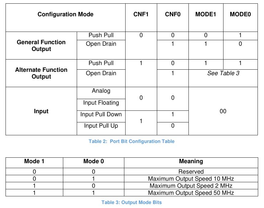
设置的对照表为:

讲解下, 比如设置 pin1, 其控制的 4 个 bits 可以设置为 0001, 对照 table2 (看下标), 可以知道, 其表示 Push Pull.

CNF 通常指 “CoNFiguration”.

在代码中设置寄存器的值, 如:

1
GPIOX->CRL = 0bXXXXXXXXXXXXXXXXXXXXXXXXXXXXXXXX

ODR 寄存器

GPIOX_ODR, 表示 “Output Data Register”, 用来控制 GPIO 端口的输出状态, 一般情况下:

  • 1 表示该引脚输出高电平 (逻辑1))
  • 0 表示该引脚输出低电平 (逻辑0))

寄存器具体细节如:

  • 0-15 位可用, 控制 pin 0-15
  • 16-31 位暂时保留不可用 (系统用)

示例, toggle GPIOA_pin5:

1
2
GPIOA->ODR &= (0b0<<5) // reset pin5
GPIOA->ODR |= (0b1<<5) // set pin5

IDR 寄存器

GPIOX_IDR, 表示 “Input Data Register”, 用于读取 GPIO 端口的输入状态 (pin 需要为 input mode). 要读取哪个就置 1.

寄存器具体细节如:

同样:

  • 0-15 位可用, 读取 pin 0-15
  • 16-31 位暂时保留不可用 (系统用)

比如:

1
2
3
#include <stdbool.h>

bool Pinx = (GPIOx->IDR & (1 << GPIOx_PIN_N)) != 0

Timers

Timers 可用于:

  • 产生精确的 time intervals
  • 测量 duration of events
  • 产生 PWM signals 等

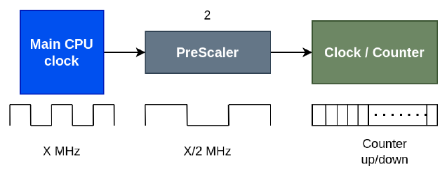
一个 timer 一般有 3 个组成部分:

  • Main CPU clock 提供一定频率的脉冲
  • PreScaler 将频率减小到想要的值
  • Counter 记录接收到的脉冲个数 (可用于计算时间, 一般情况下, 设置当 counter 到达一定值时触发一个 event)

下图是 STM32 F103RB 的 clock tree:
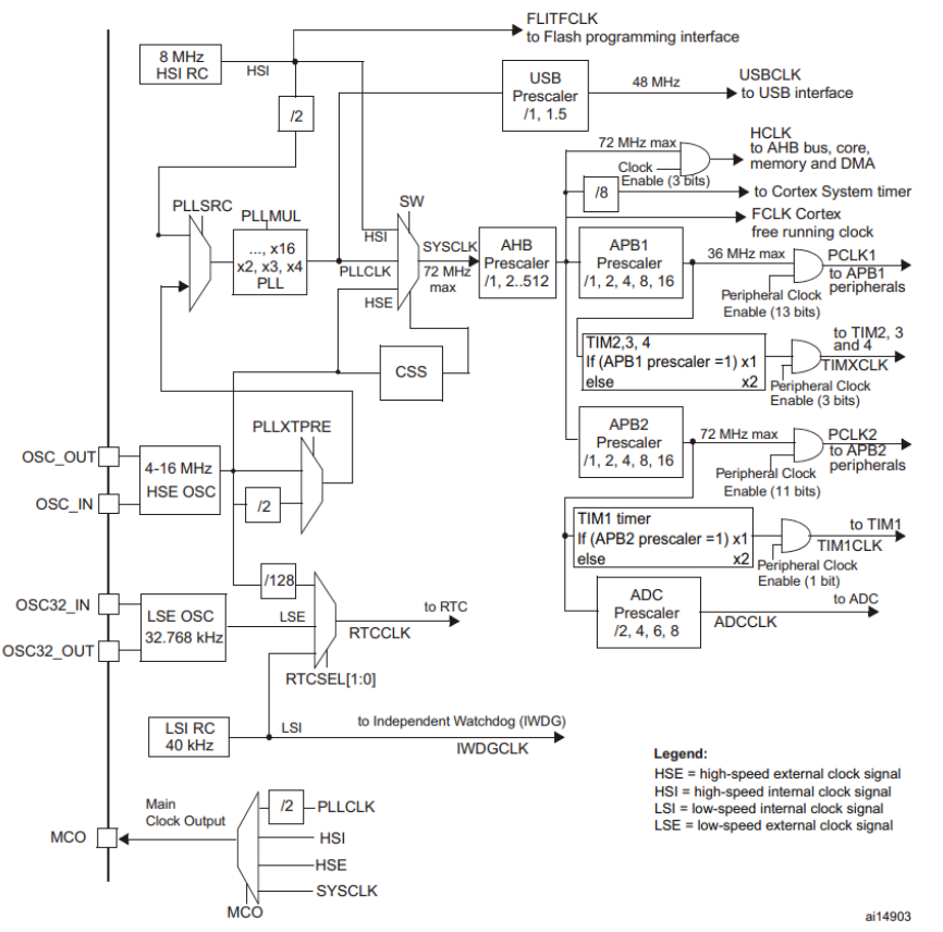
  • 不同的 timers (prescaler 不同) 都连接到 CPU clock

这里以 TIM2, 3 和 4 为例说明:

  • 都为 16 位计时器, 意味着能够计数的范围是从 0 到 65535 ($2^{16} - 1$)
  • 每个定时器最多可以支持 4 个输入捕获 (IC), 输出比较 (OC), 脉宽调制 (PWM) 或脉冲计数器功能, 以及增量编码器输入

一个示例:

主频为 80MHz, 要求 prescaler 和 counter 都是 16 位, 且 2.5s 触发一次 event, 求 prescaler 和 counter 的可能值

因为 prescaler 和 counter 是 16 位, 因此其取值为 0~65535 ($2^{16}-1$), 设 prescaler 为 8000, 则:
$$
\displaylines
{
\begin{aligned}
prescaler\ frequency = \frac{80MHz}{8000} = 10000Hz
\end{aligned}
}
$$

计算 counter 的值为:
$$
\displaylines
{
\begin{aligned}
interval = \frac{1}{10000Hz} = 0.0001s \newline~ \newline
counter\ value = \frac{2.5s}{0.0001s} = 25000
\end{aligned}
}
$$

具体示例

NUCLEO-F103RB 的默认 clock tree 为:
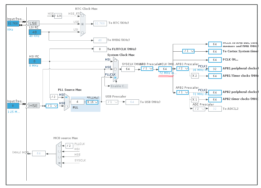
  • 默认 prescaler 为 1, 频率 64MHz, 最大可为 72MHz

对 TIM2 的配置示例:
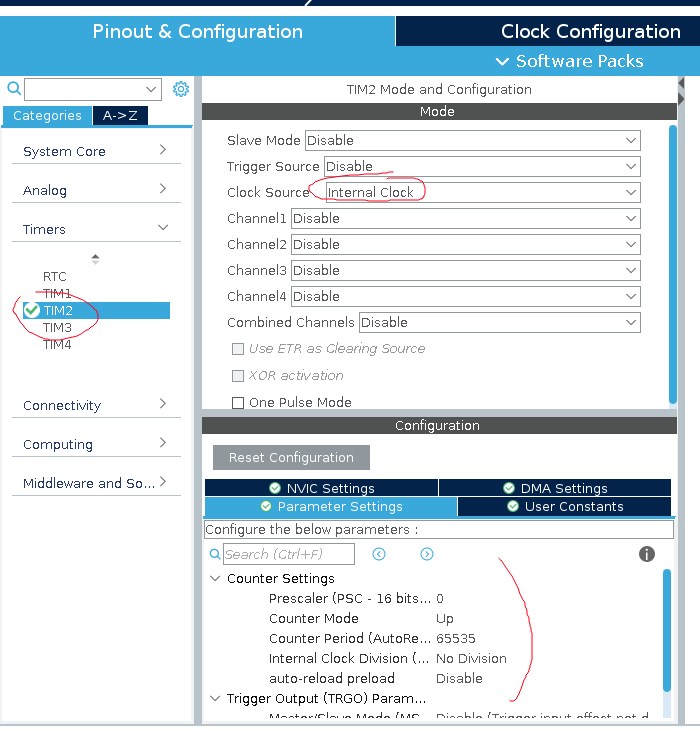
注意, 这里的 prescaler 和 counter 值总是比自己想设的小 1. (也就是说这里写的 0, 实际上是 1)

在生成代码后, 可以用:

1
HAL_TIM_Base_Start(&htim2).

来启用 timer. 如:

1
2
3
4
5
6
7
8
9
10
11
12
13
14
15
16
17
18
// starting the timer
HAL_TIM_Base_Start(&htim2);

// getting the timer value
uint_16t timer_val = __HAL_TIM_GET_COUNTER(&htim2);
/* USER CODE END */

/* Infinite loop */
/* USER CODE BEGIN WHILE */
while (1)
{
// Checking the value of the counter if reached the counter period
if ((__HAL_TIM_GET_COUNTER(&htim2) - timer_val) >= 1000) {
HAL_GPIO_TogglePin(GPIOA, GPIO_PIN_5);
timer_val = __HAL_TIM_GET_COUNTER(&htim2);
}
/* USER CODE END WHILE */
}

(注意这里的写法不规范, 有一个问题, 当到 if 时, timer 不是想要的值, 就往下执行, 但往下执行到某处时, timer 值可能已经重置了, 此时又返回 if 又执行不了)

  • timer_val 存储的是上一次用于比较的值, 当变化超过 1000 时触发

这里使用 timer 的好处在与其 unblocking, 不会阻断其他程序运行.

Interrupt

中断可来自外部, 如:

  • button press
  • sensor output

也可来自内部, 如:

  • timer overflow
  • data transfer completion

当中断发生时, microcontroller 会 suspend 当前任务, 转去处理中断任务, 待完成后, 又从中断处继续运行.

Timer Interrupt (Internal)

Counter 计数如:

(ISR 指 “Interrupt Service Routine”, 即中断服务程序)

  • 也就是说, counter 到一定数之后, 就触发一次中断

启用 timer 的中断功能需要配置 NVIC (Nested Vector Interrupt Controller, 嵌套向量中断控制器), 如:
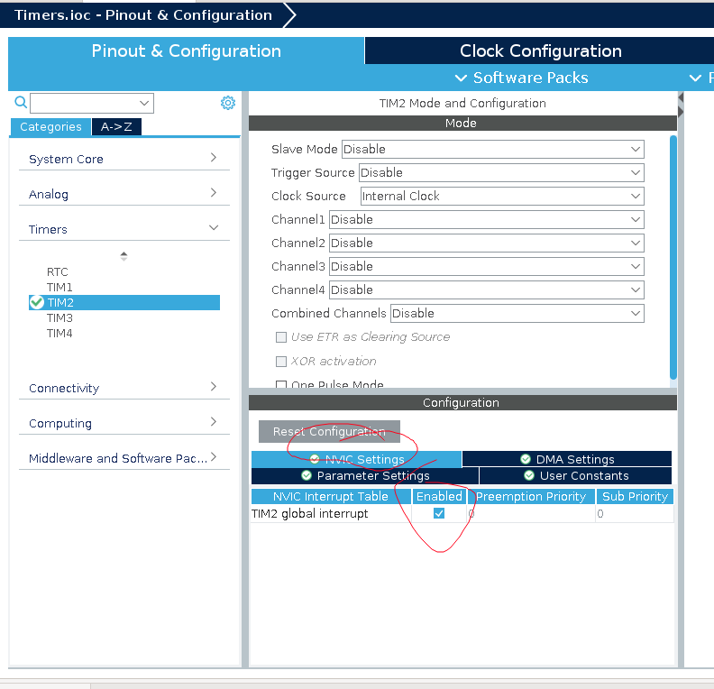
此时启动 timer 需要用:

1
HAL_TIM_Base_Start_IT(&htim2);

一个中断函数的示例:

1
2
3
4
5
void HAL_TIM_PeriodElapsedCallback(TIM_HandleTypeDef *htim) {
if (htim == &htim2) {
HAL_GPIO_TogglePin(GPIOA, GPIO_PIN_5);
}
}

(这个函数名应该要查表)

  • 这里会先检查触发中断的计时器是否为 TIM2

这个函数会由 timer 定时触发 (看前面的图就知道了, 这个函数就是 ISR).

Interrupt (External)

这个外部中断由 GPIO Pin 来触发, 比如:

  • falling edge
  • rising edge
  • changing edge

设置一个 pin 为 Interrupt pin:
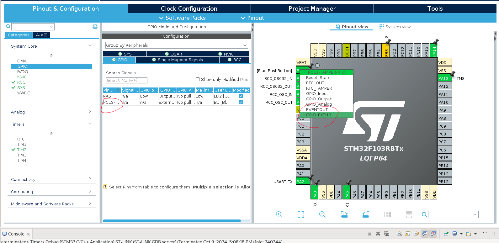
  • 点 PC13, 选 GPIO_EXTI13

选择触发 Interrupt 的方式 (即什么时候运行 ISR):
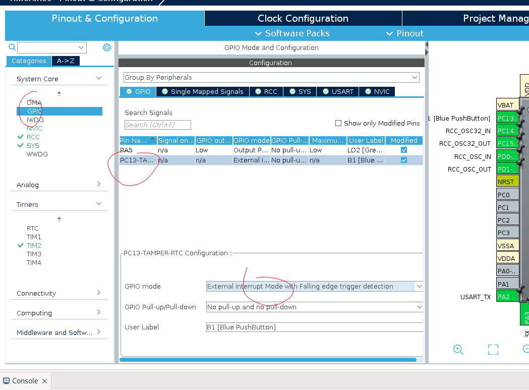
还要确保 NVIC 是注册了的:
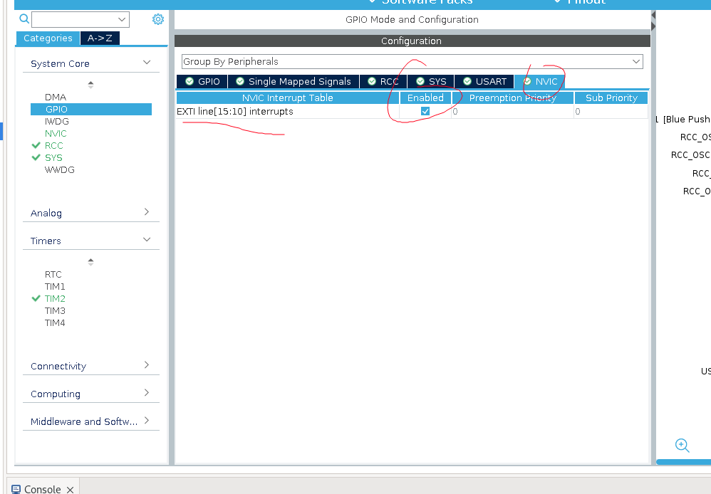
注意这里的 EXTI_line[15:10]:

  • EXTI_line 是用于连接外部引脚 (如 GPIO 引脚) 到中断控制器的. 每一条线可以配置为响应特定引脚的状态变化 (例如上升沿, 下降沿或双边沿)
  • [15:10] 指哪几条线, 这里表示 EXTI 控制器中第 10 到第 15 号线. STM32 通常支持多条 EXTI 线, 可以用于多个 GPIO 引脚

当前已注册的 Interrupts 可以在 CubeIDE 的 core>source>stm32f1xx_it.c 文件中查看:
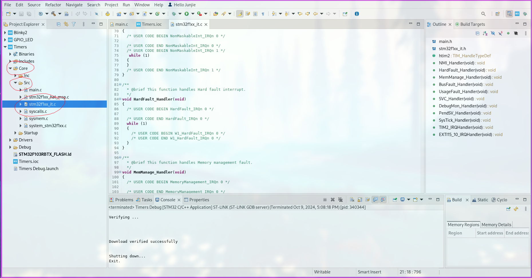
这里也能看到 timer 和 external interrupt handlers:
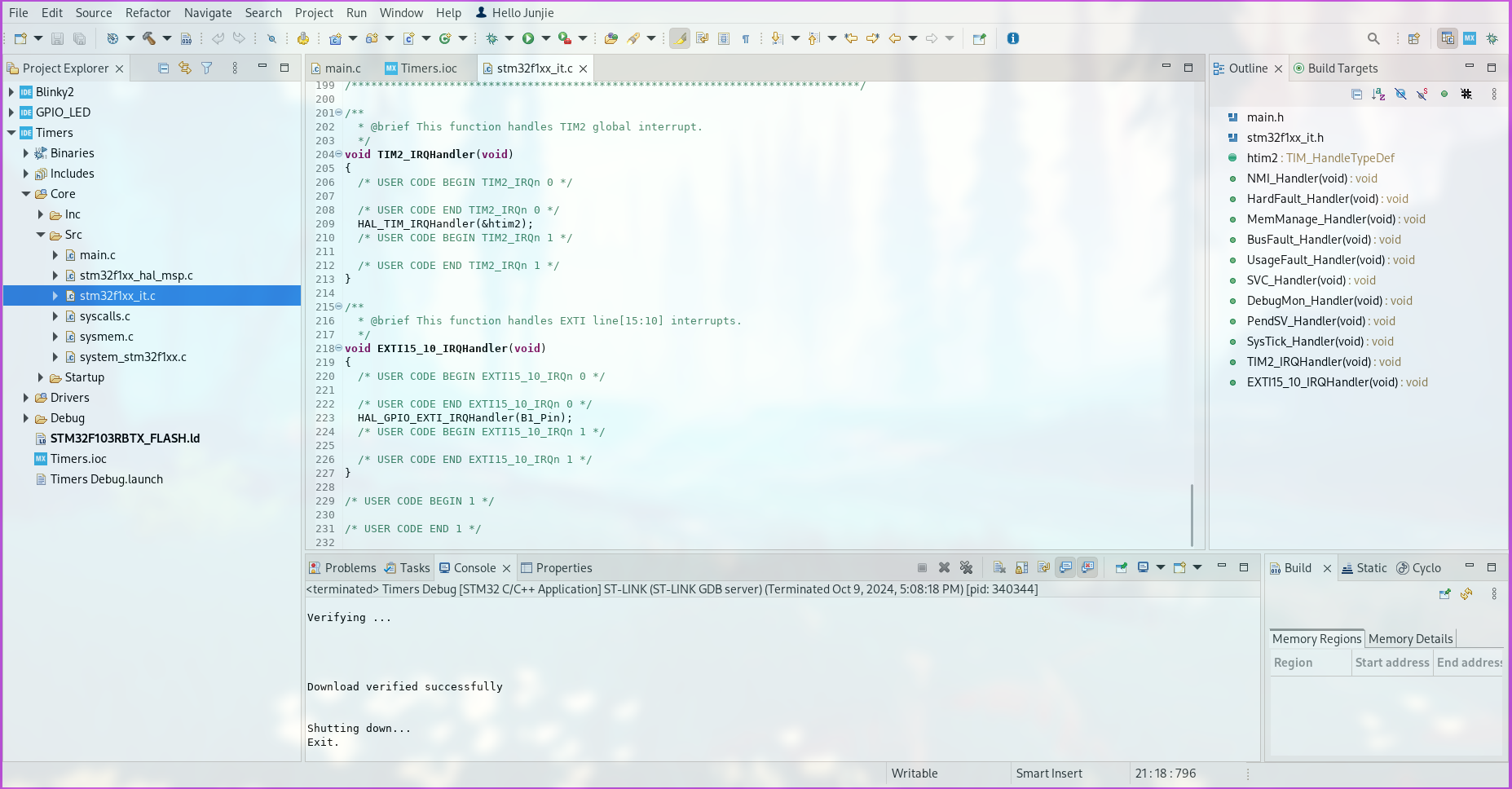
这里的 B1_Pin 实际上指前面的 PIN_13, 只是因为其 Label 为 B1, 所以这里为这个名字.
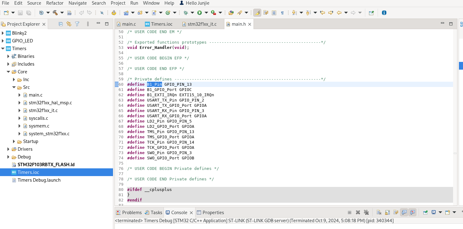
右键 HAL_GPIO_EXTI_IRQHandler 函数并选中 Open Declaration, 可以看到:
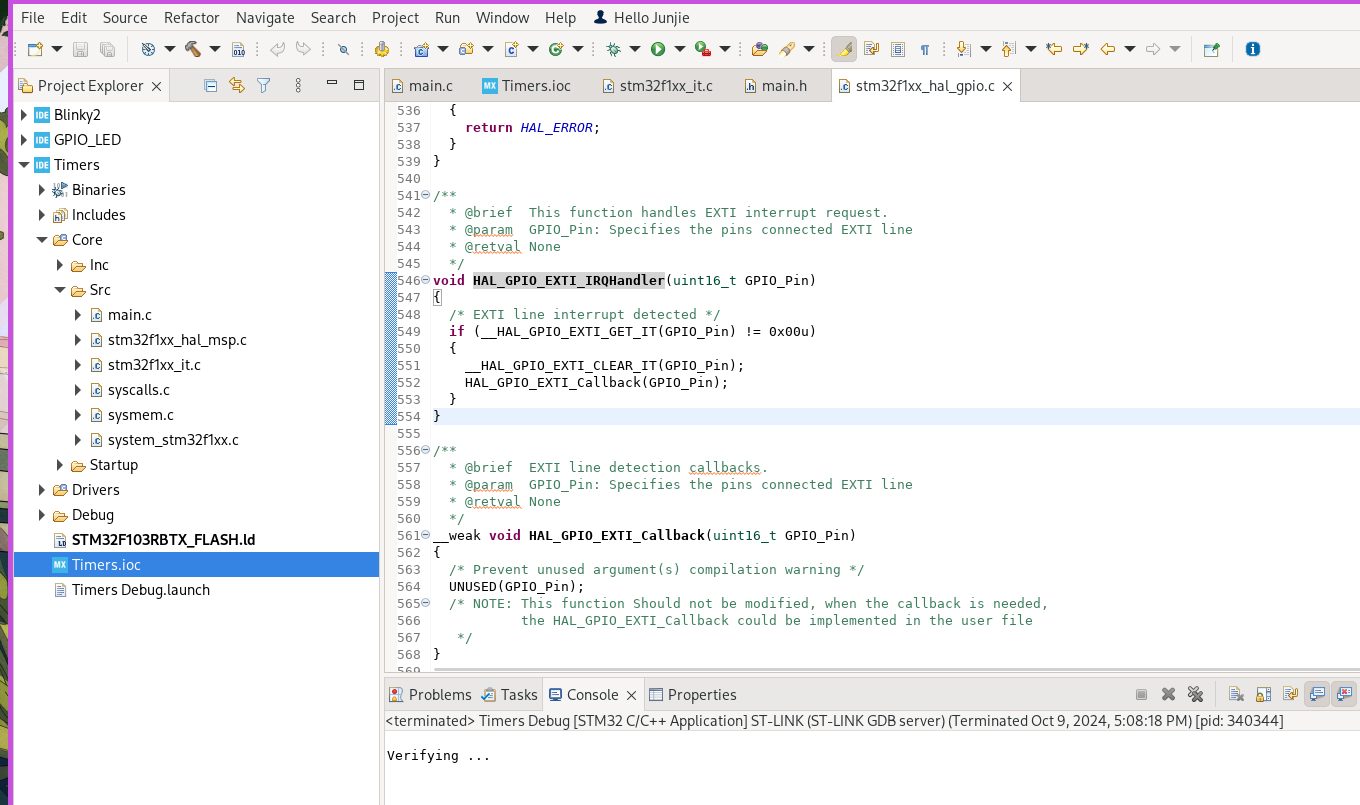
  • 实际上执行中断的函数是 HAL_GPIO_EXTI_Callback

因此, 我们在 main.c 中定义这个函数即可, 如:

1
2
3
void HAL_GPIO_EXTI_Callback(uint16_t GPIO_Pin) {
HAL_GPIO_TogglePin(GPIOA, GPIO_PIN_5);
}

几个与 interrupt 相关的函数

1
2
3
4
5
6
7
void HAL_GPIO_EXTI_Callback(uint16_t GPIO_Pin) {
if (HAL_TIM_Base_GetState(&htim2) == HAL_TIM_STATE_READY) {
HAL_TIM_Base_Start_IT(&htim2);
} else {
HAL_TIM_Base_Stop_IT(&htim2);
}
}
  • HAL_TIM_Base_GetState, 用于获取 TIM 内部中断的状态
  • HAL_TIM_STATE_READY 是一个宏定义, 表示 TIM 内部中断的状态
  • HAL_TIM_Base_Start_IT 用于启用 TIM 内部中断
  • HAL_TIM_Base_Stop_IT 用于暂停 TIM 内部中断

UART

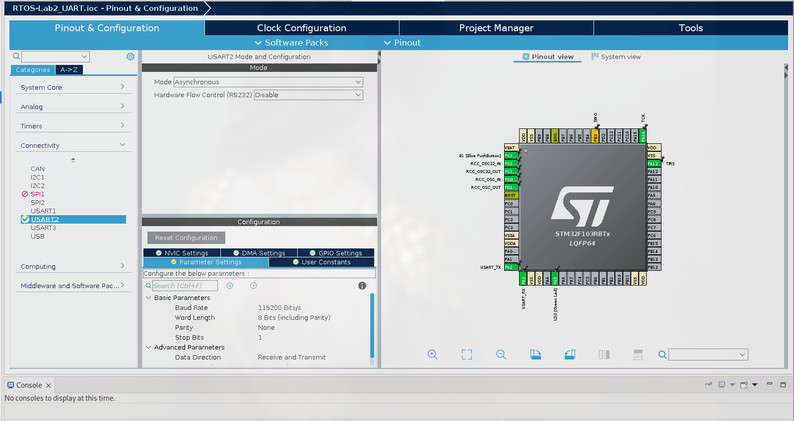
在 CubeMX 的配置图示意如下:

数据传输

在 HAL 库中, 用 UART 传输数据的函数为:

1
HAL_UART_Transmit(&uart_port, (string_pointer*)string, string_lenght, DELAY);
  • DELAY 是一段确认数据已经传送完成的时间

一段示例代码, 发送 “hello world”:

1
2
3
4
5
6
7
8
9
10
11
12
13
14
15
16
17
18
19
20
21
22
23
24
25
26
27
#include "main.h"

/* USER CODE BEGIN Includes */
#include <string.h>
#include <stdio.h>
/* USER CODE END Includes */
...
...
/* USER CODE BEGIN 1 */
int num = 0;
char char_str[] = "hello world";
char num_str[10];
/* USER CODE END 1 */
...
...
while (1)
{
num = num + 1; // addming every time a new hello world is printed
sprintf(num_str, " %hu\n", num); // converting int to string
// transmitting to the UART PORT 2
HAL_UART_Transmit(&huart2, (uint8_t*)char_str, strlen(char_str), HAL_MAX_DELAY);
HAL_UART_Transmit(&huart2, (uint8_t*)num_str, strlen(num_str), HAL_MAX_DELAY);
HAL_Delay(1000); // delay of a second

/* USER CODE END WHILE */
/* USER CODE BEGIN 3 */
}
  • 注意这里格式化输出的占位符 %hu, %h 表示 short 类型, u 表示 unsigned 类型 (即输出一个 unsigned short, 范围在 0-65535)

数据接收

对于接收方而言, 有三种接收方式:

  • Polling method, 在接收到数据之前一直 blocks the CPU
  • Interrupt method, 在得知数据发送到时用中断处理数据
  • Direct Memory Access (DMA), 数据直接经 DMA 传输到 memory

这里以 Interrupt method 为例, 需要先在 NVIC 部分进行配置, 开启中断:
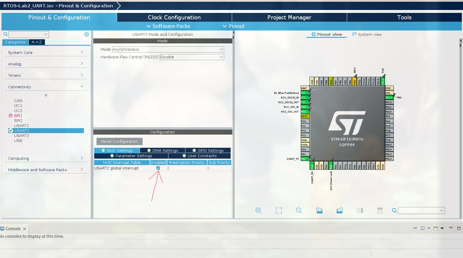
(注意这里也设置 BAUD Rate 为 9600)

与 UART 数据接收相关的 HAL 函数为:

1
HAL_UART_Receive_IT (&huart, rx buffer, no. of bits)
  • rx_buffer 指存储数据的位置 (一个变量)
  • no. of bits 指要接收的数据长度

相对应的中断处理函数为:

1
void HAL_UART_RxCpltCallback(UART_HandleTypeDef *huart)

同样举一个示例, 发送一个 ID, 并在接收后打印到 serial monitor, 部分代码如下:

1
2
3
4
5
6
7
8
9
10
11
12
13
14
15
16
17
18
19
20
...

/* Private variables ---- */
UART_HandleTypeDef huart2;
/* USER CODE BEGIN PV */
uint8_t rx_data[10];
...

/* USER CODE BEGIN 2 */
HAL_UART_Receive_IT(&huart2, rx_data, 9);

...

void HAL_UART_RxCpltCallback(UART_HandleTypeDef *huart)
{
HAL_UART_Transmit(&huart2, (uint8_t*)rx_data, strlen(rx_data), HAL_MAX_DELAY);
HAL_GPIO_TogglePin(GPIOA, GPIO_PIN_5);
rx_data[0] = '\0';
HAL_UART_Receive_IT(&huart2, rx_data, 9);
}
  • while 循环外调用 HAL_UART_Receive_IT 是为了启用中断接收 UART 数据
  • 每次运行 HAL_UART_Receive_IT(&huart2, rx_data, 9); 之后, 都会触发 HAL_UART_RxCpltCallback 函数

之后启用一个 Serial Monitor, 比如在 Linux 上就可以用 cutecom:
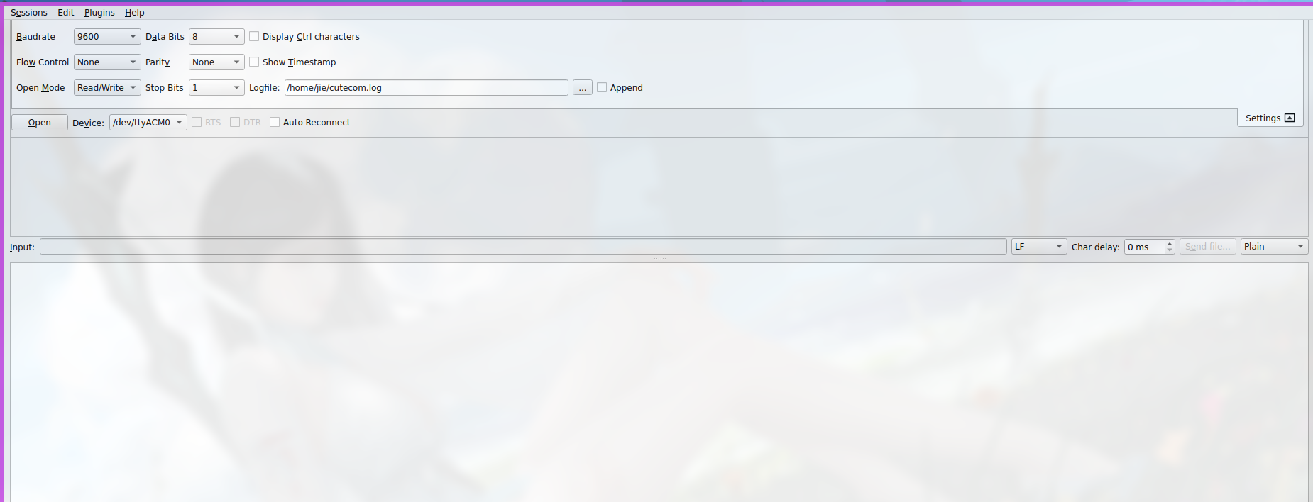
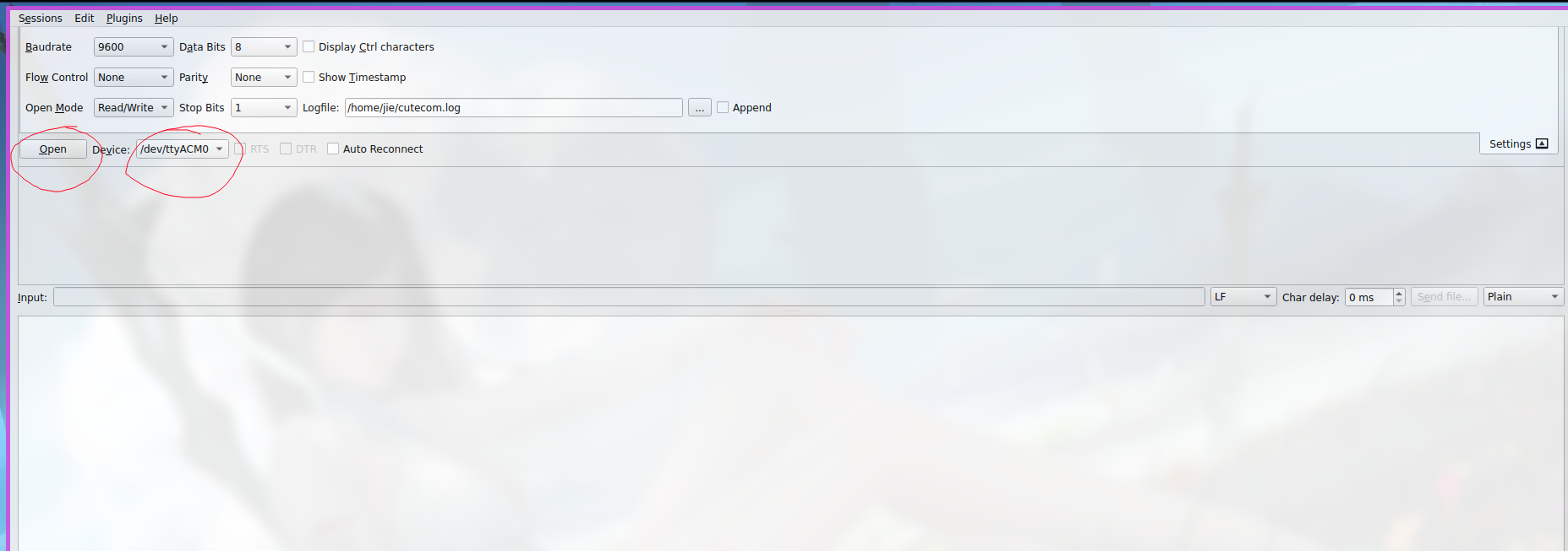
之后发送数据即可.
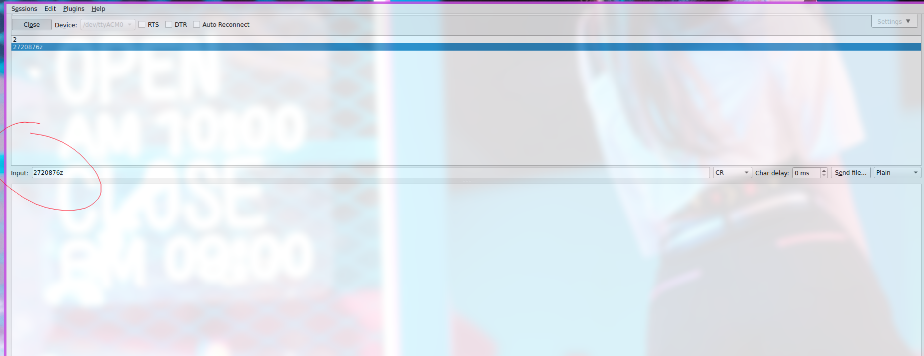
可以看到回显:
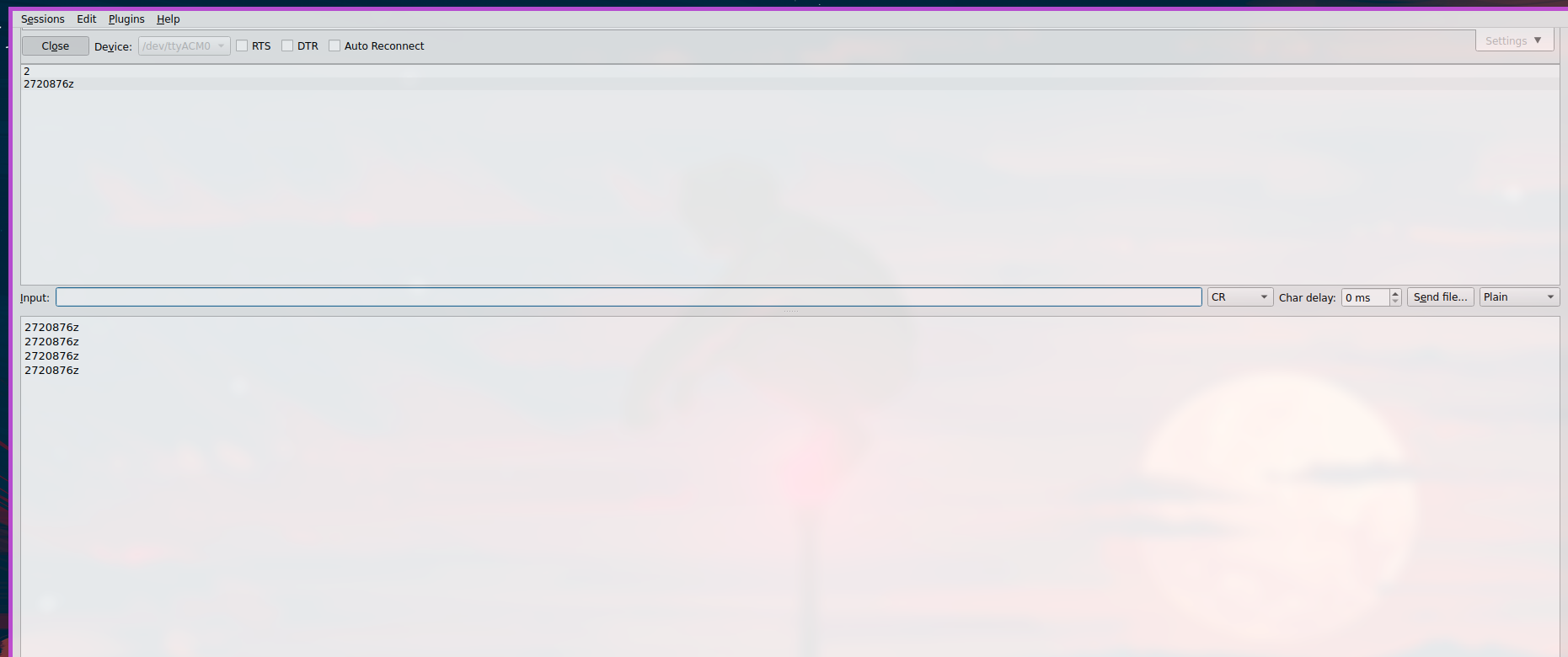
神秘错误

strlen((char*)rx_data) 导致回显消失

1
HAL_UART_Transmit(&huart2, rx_data, strlen(rx_data), HAL_MAX_DELAY);

正常, 但:

1
HAL_UART_Transmit(&huart2, rx_data, strlen((char*)rx_data), HAL_MAX_DELAY);

会导致在第三次打印时回显消失???

I2C

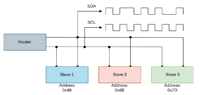
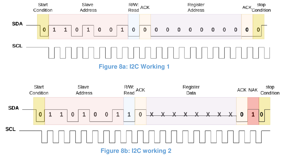
HAL 库中, 使用 I2C 传输和接收数据的函数为:

1
2
HAL_I2C_Master_Transmit(&hi2c#, I2C_Slave_address, buffer, #_of_bytes, DELAY);
HAL_I2C_Master_Receive(&hi2c#, I2C_Slave_address, buffer, #_of_bytes, DELAY);
  • &hi2c# 指要使用的 I2C 接口
  • buffer 是要发送的数据或要存储到的位置
  • #_of_bytes 指数据长度, 注意这里是 bytes 而非 bits
  • DELAY 是确保 communication session 结束的时间

这里以, 用 NUCLEO-F103RB Board 发送数据给 Arduino 来观察现象 (Arduino 的代码在课程文件里), 为示例, Arduino 接收到的信息和要做的行为如下:

Value Action
0x83 Blink built in LED once a second
0x82 Blink built in LED once 75 ms
0x81 Blink built in LED once a 500 ms
0x80 LED to remain on
0x00 Address of analog value measured by Arduino
0x01 Address of 4 bytes of message in the Arduino

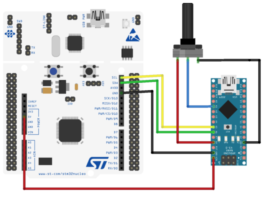
接线为:

具体为:

  • Nucleo SCL => ARDUINO A5
  • Nucleo SDA => ARDUINO A4
  • Nucleo GND => GND
  • Variable Resistor out => Arduino A1

注意这里 Arduino 的 programmer 配置为:
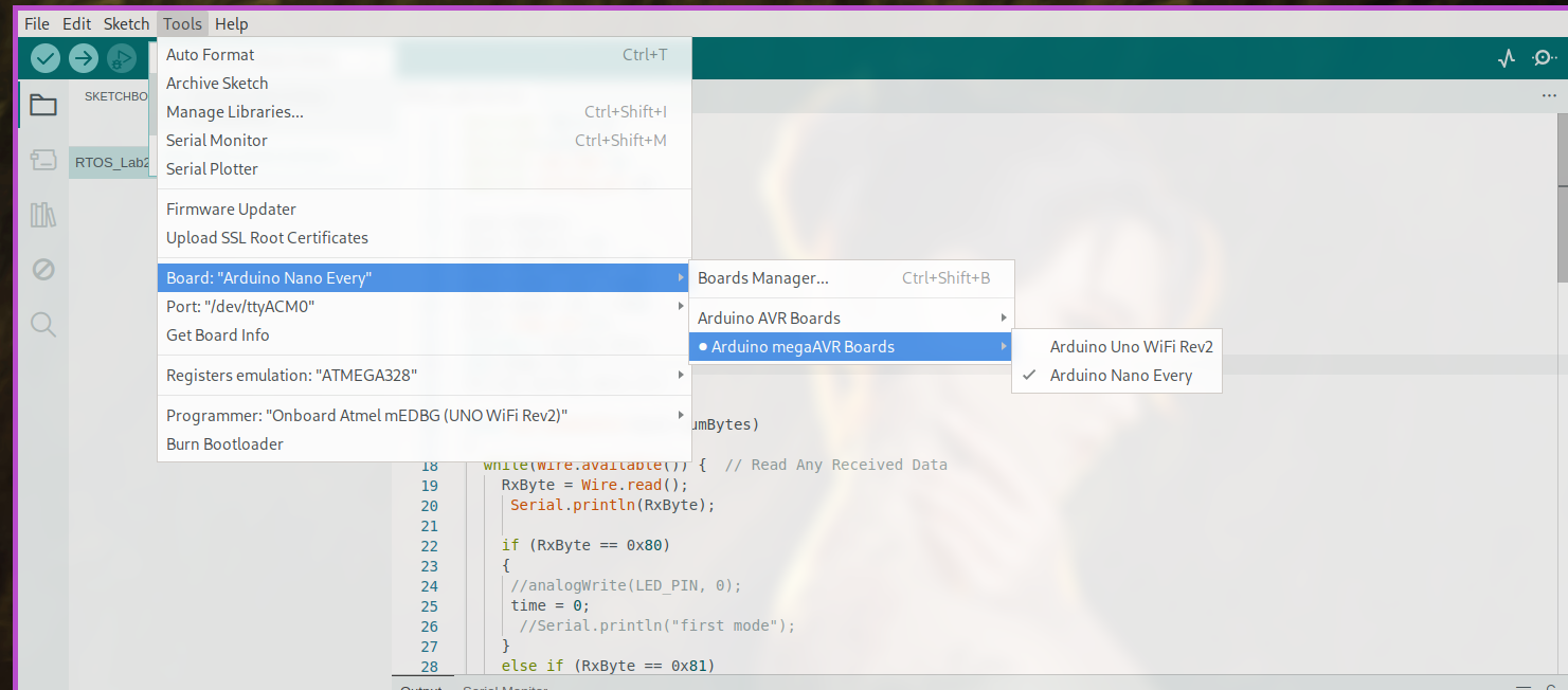
之后对 NUCLEO-F103RB 的引脚设置如:
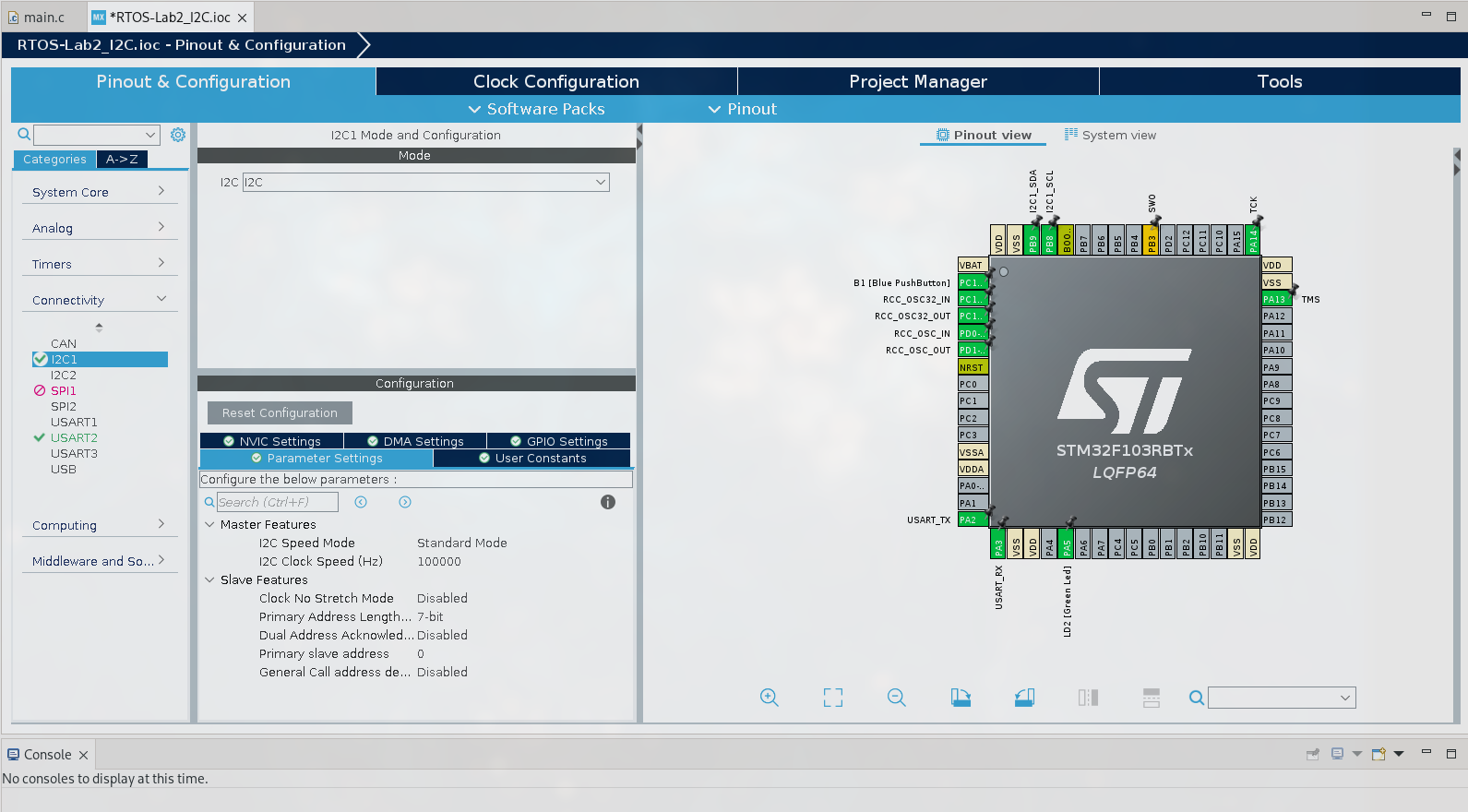
相关变量的设置代码如下:

1
2
3
4
5
6
7
8
9
10
11
12
13
14
15
16
17
18
19
20
21
22
23
#include <main.h>
#include <string.h>
#include <stdio.h>
...
...
int main(void)
{
/* USER CODE BEGIN 1 */
HAL_StatusTypeDef ret;
static const uint8_t nano_addr = 0x55 << 1; // left shifting as bit0 used to indicate read write
uint8_t buff[12]; // Buffer ti receive and send 8 bit data
uint8_t cmd_buff[12]; // buffer save the data when a command sent
uint8_t analog_buff[12]; // buffer to save analog data
uint8_t message_buff[12]; // buffer to save the message received
uint16_t analog_val; // 16 bit analog value
uint8_t cmd_0 = 0x83; // send to make the LED blink once a second
uint8_t cmd_1 = 0x82; // send to make the LED blink once 750 ms
uint8_t cmd_2 = 0x81; // send to make the LED blink once 500 ms
uint8_t cmd_3 = 0x80; // send to make the LED to remain on

uint8_t REG_0 = 0x0; // receive analog value
uint8_t REG_1 = 0x1; // Receive the message
}
  • HAL_StatusTypeDef ret, 是一个用来存储 communication 是否成功的 flag
  • nano_addr 表明 Arduino nano slave 的地址, << 1 表明第八位是 0 即向从机发送数据, 若是 1 则是从从机读取数据

while 中的部分代码如下:

1
2
3
4
5
6
7
8
9
10
11
12
13
14
15
16
17
18
19
20
21
22
23
24
25
26
27
28
29
30
31
32
33
34
// sending the command to adjust the light blinking speed
buff[0] = REG_0; // adding blinking command to the buffer
ret = HAL_I2C_Master_Transmit(&hi2c1, nano_addr, buff, 1, HAL_MAX_DELAY);

if (ret != HAL_OK) // if communication not successful
{
strcpy((char*)buff, "Error Rx1\n");
HAL_UART_Transmit(&huart2, buff, strlen((char*)buff), HAL_MAX_DELAY);
}
else // if communication successful
{
HAL_Delay(500); // delay
nano_addr |= 0b1;
// receiving 2 bytes via i2c
ret = HAL_I2C_Master_Receive(&hi2c1, nano_addr, buff, 2, HAL_MAX_DELAY);
if ( ret != HAL_OK ) // if communication not successful
{ // printing error on the serial monitor
strcpy((char*)buff, "Error Rx2\n");
HAL_UART_Transmit(&huart2, buff, strlen((char*)buff), HAL_MAX_DELAY);
}
else // if communication successful
{
// converting the data received into the actual value
analog_val = buff[1];
analog_val = buff[0] | (analog_val << 8);
sprintf(analog_buff, " %hu\n", analog_val);
HAL_UART_Transmit(&huart2, analog_buff, strlen((char*)analog_buff), HAL_MAX_DELAY);
}
}
// reseting buffer
memset(buff, '\0', sizeof(buff));

// delay of 2 seconds
HAL_Delay(2000);
  • 这里用了 serial monitor 来调试

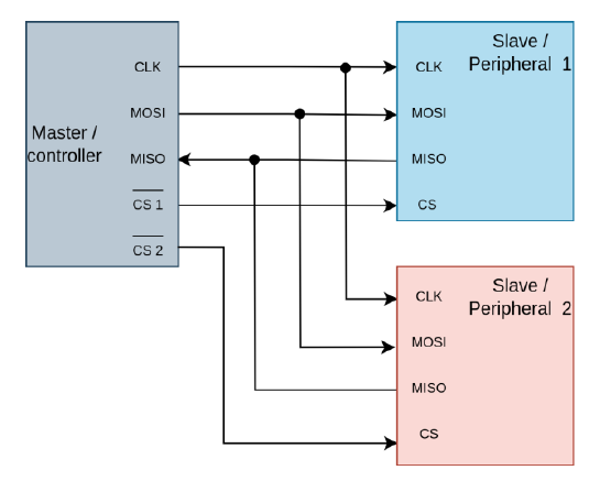
SPI

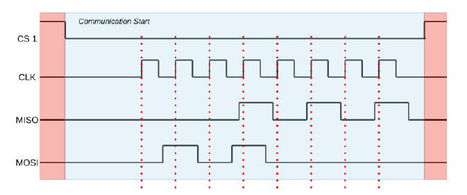
可以看到发送和接收数据可以同时进行.

HAL 库中用于处理 SPI 的函数为:

1
2
HAL_SPI_Transmit(&hspi#, buffer, # of bits, delay);
HAL_SPI_Receive(&hsp#, buffer, # of bits, delay);

(注意和 I2C 的区别, 没有 address, 要发给哪个 slave 靠拉低 CS 线)

下面同样有一段示例, main 函数中的部分代码为:

1
2
3
4
5
6
7
8
9
10
11
int main(void)
{
uint8_t buff[12]; // Buffer to receive and send 8 bit data
uint16_t analog_val; // 16 bit analog value
uint8_t cmd_0 = 0x83; // send to make the LED blink once a second
uint8_t cmd_0 = 0x82; // send to make the LED blink once 750 ms
uint8_t cmd_0 = 0x81; // send to make the LED blink once 500 ms
uint8_t cmd_0 = 0x80; // send to make the LED to blink once every 250 ms
uint8_t reg_0 = 0x0; // make the lower byte ready to be transfered
uint8_t reg_1 = 0x1; // make the higher byte ready to be transfered
}

while 中的部分代码为:

1
2
3
4
5
6
7
8
9
10
HAL_GPIO_WritePin(GPIOB, GPIO_PIN_6, GPIO_PIN_SET);
while (1)
{
HAL_GPIO_WritePin(GPIOB, GPIO_PIN_6, GPIO_PIN_RESET);
memset(buff, '\0', sizeof(buff));
buff[0] = cmd_0;
HAL_SPI_Transmit(&hspi1, buff, 1, HAL_MAX_DELAY);
HAL_GPIO_WritePin(GPIOB, GPIO_PIN_6, GPIO_PIN_SET);
HAL_Delay(100);
}

完成一组交替的通信:

1
2
3
4
5
6
7
8
9
10
11
12
13
14
15
16
17
18
19
20
21
22
23
24
25
26
27
28
29
30
31
32
33
34
35
36
37
// sending the Address
HAL_GPIO_WritePin(GPIOB, GPIO_PIN_6, GPIO_PIN_RESET);
memset(buff, '\0', sizeof(buff));
buff[0] = 0x0;
HAL_SPI_Transmit(&hspi1, buff, 1, HAL_MAX_DELAY);
HAL_GPIO_WritePin(GPIOB, GPIO_PIN_6, GPIO_PIN_SET);
HAL_Delay(100);

// Receiving the Data of the Address sent
memset(buff, '\0', sizeof(buff));
HAL_GPIO_WritePin(GPIOB, GPIO_PIN_6, GPIO_PIN_RESET);
HAL_SPI_Receive(&hspi1, buff, 1, HAL_MAX_DELAY);
HAL_GPIO_WritePin(GPIOB, GPIO_PIN_6, GPIO_PIN_SET);
analog_val = buff[0];
HAL_Delay(100);

// sending the Address
memset(buff, '\0', sizeof(buff));
buf[0] = 0x1;
HAL_GPIO_WritePin(GPIOB, GPIO_PIN_6, GPIO_PIN_RESET);
HAL_SPI_Transmit(&hspi1, buff, 1, HAL_MAX_DELAY);
HAL_GPIO_WritePin(GPIOB, GPIO_PIN_6, GPIO_PIN_SET);
HAL_Delay(100);

// Receiving the Data of the Address sent
memset(buff, '\0', sizeof(buff));
HAL_GPIO_WritePin(GPIOB, GPIO_PIN_6, GPIO_PIN_RESET);
HAL_SPI_Receive(&hspi1, buff, 1, HAL_MAX_DELAY);
HAL_GPIO_WritePin(GPIOB, GPIO_PIN_6, GPIO_PIN_SET);
HAL_Delay(100);

analog_val = (buff[0] << 8) | (analog_val);
memset(buff, '\0', sizeof(buff));
sprintf(buff, " %hu\n", analog_val);

// printing data
HAL_UART_Transmit(&huart2, buff, strlen((char*)buff), HAL_MAX_DELAY);

PWM

在 STM32 中, PWM 是借助 Timer 产生的.

这里的示例, 折纸 PWM 的频率为 $10Hz$, 已知 internal clock 为 $64MHz$, 因此 prescaler 和 counter 可以设置为:
$$
\displaylines
{
\begin{aligned}
just\ let\ prescaler\ = 64000 \newline~ \newline
frequency\ after\ prescaler\ = \frac{64MHz}{1000} = 1000 \newline~ \newline
counter = \frac{1000}{10} = 100
\end{aligned}
}
$$

设置如下:
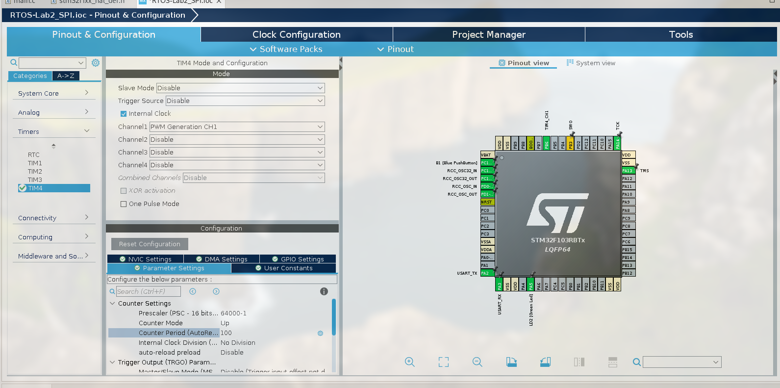
部分代码如下:

1
2
3
4
5
6
7
8
9
10
11
12
13
HAL_TIM_PWM_Start(&htim4, TIM_CHANNEL_1);
uint_16t duty_cycle = 10;

while (1)
{
duty_cycle += 10;
if (duty_cycle == 100) {
duty_cycle = 10;
}

htim4.Instance->CCR1 = duty_cycle;
HAL_Delay(1000);
}

注意每个 timer 的每个 channel 都对应一个 pin, 这里的是 PB8 (以 NUCLEO-F103RB 为例)

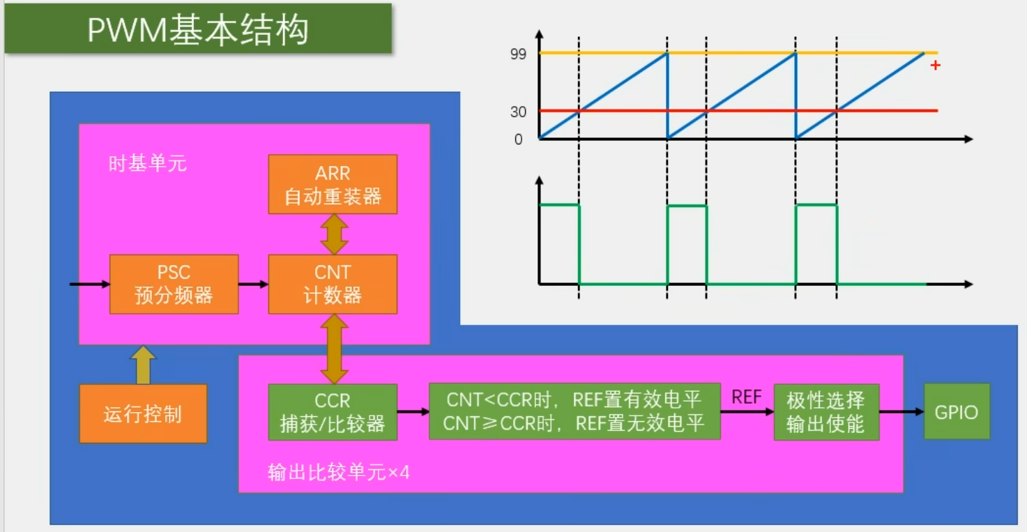
  • HAL_TIM_PWM_Start() 用于启用 PWM
  • htim4.Instance->CCR1
    • Instance 成员用于获取定时器硬件寄存器的基地址
    • CCR1 (Capture/Compare Register 1) 是捕获/比较寄存器, 这里用来设置 PWM 占空比
STM32CubeIDE-基本使用
http://example.com/2024/09/26/STM32CubeIDE-基本使用/
作者
Jie
发布于
2024年9月26日
许可协议